

These enclosures are primarily used with the function of:
? Derivation and/or cables collecting from the field and to the control rooms, for analogic signals and/or digital
signals end/or measure signals what thermocouples, signals 4 ÷ 20 mA etc. etc.
? Clearing barrier signals and/or of transposition signals from field to control room what Fild-Bus; Mod-Bus and
Profi-Bus
? Control and start-stop of apparatus as motors, fans, pumps etc. etc.
? Reading of physical greatness which flow, level, pressure, temperature,current, voltage, frequency, speed control
etc. etc.
? Offering customers a great combination of possibilities and flexibility.
Service hotline:
0523-88317000 88318288
-
DescriptionEJT*-R Series enclosures for Dust explosion proof power distribution, switchgear and control unit combinations with terminal boxes in the type of protection "Protection by Enclosure tb".
The program comprising different enclosures is designed for use in dust explosion-hazardous areas of Zones 21 and 22 according to IEC 60079-0 and IEC 60079-31. The enclosures are made of polyester. Adapted to the installation requirements, the power distributions can be installed in customer specific wall as well as standing structures.
Normal commercial industrial switchgear which under operating conditions generate electric arcs and sparks can be built into dust explosion proof enclosures. These can be equipped with command status devices, shafts for
operating circuit-breakers and viewing windows. However, all built-in devices in the enclosure walls (enclosure housing) must correspond to a standardized type of protection – at least of the category 2D according to
Guideline 2014/34/EU. The inlet flanges are equipped with cable and conductor entry fittings – within the framework of the certified maximum number – according to the user's requirements.
These enclosures are primarily used with the function of:
? Derivation and/or cables collecting from the field and to the control rooms, for analogic signals and/or digital
signals end/or measure signals what thermocouples, signals 4 ÷ 20 mA etc. etc.
? Clearing barrier signals and/or of transposition signals from field to control room what Fild-Bus; Mod-Bus and
Profi-Bus
? Control and start-stop of apparatus as motors, fans, pumps etc. etc.
? Reading of physical greatness which flow, level, pressure, temperature,current, voltage, frequency, speed control
etc. etc.
? Offering customers a great combination of possibilities and flexibility.Technical parameterTechnical parameterTechnical parameterTechnical parameterTechnical parameter
Technical parameter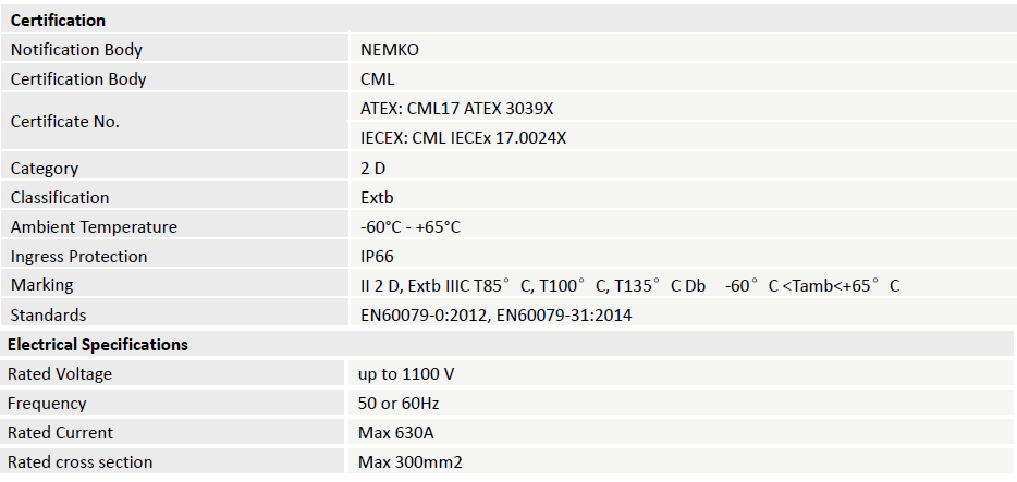
depending on type of terminal and explosions-proof components used.
Accessories and special execution on request
? Special hardware in stainless steel AISI 316 A4
? Out of standard thread
? Set of nut and basket for restoration of the IP66 degree of protection(only for metric holes)
? ANSI B.20.1 NPT or UNI EN 10226-2 Conic Gas adapters with Metric or vice versa.
? Unified joining flange for various enclosures, inclusive of gaskets for IP 66 degree of protection and stainless
steel Inox AISI 304 fixing screws.
? Galvanized steel internal plate
? Insulation material internal plate
? Passing earthing bolt
? Hinges
Thread and hubs
? ISO 261/ISO 965 Metric thread
Passing holes, suitable for ISO 261/ISO 965 Metric thread -
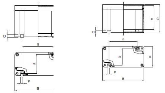
-
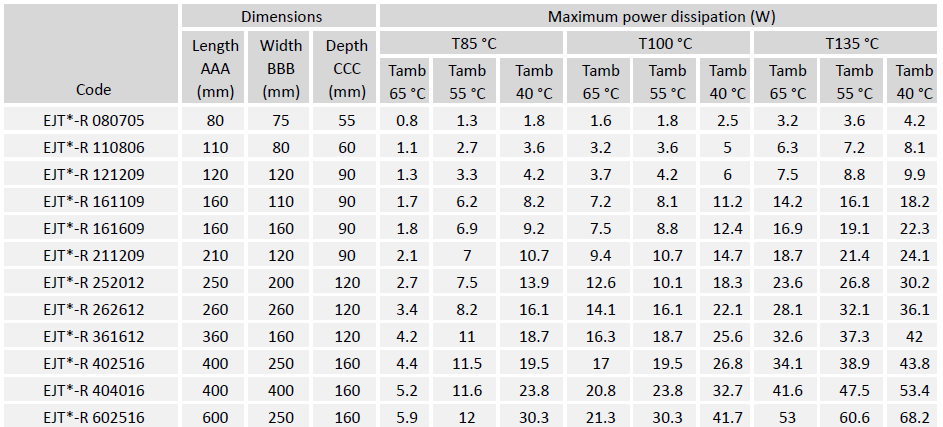
The junction boxes & control stations may also be manufactured to intermediate sizes. This assumes that any given dimension is not larger than the respective dimension of the largest enclosure or smaller than the respective dimension of the smallest enclosure. The power rating applied to a junction box of intermediate size is that of the next smallest enclosure.
The terminal and components may be used in specified combinations subject to the calculation of maximum dissipated power and the conditions of certification listed. The maximum dissipated power for each enclosure is detailed above.
The enclosures can be drilled and taped with the maximum size and maximum number of holes as specified in the manufacturer documents for the use with separately certified cable glands or blanking plugs. Each enclosure is provided with an internal earthing certified terminal or earthing point. Metal enclosures are provided with an external earthing point.
The enclosures EJT*-R series have modular dimensions and can be jointed together through a flange that continies to grant the IP protection. With such system we’re able to increase the internal volume available for electrical installation so to reach the sole space reallly needed.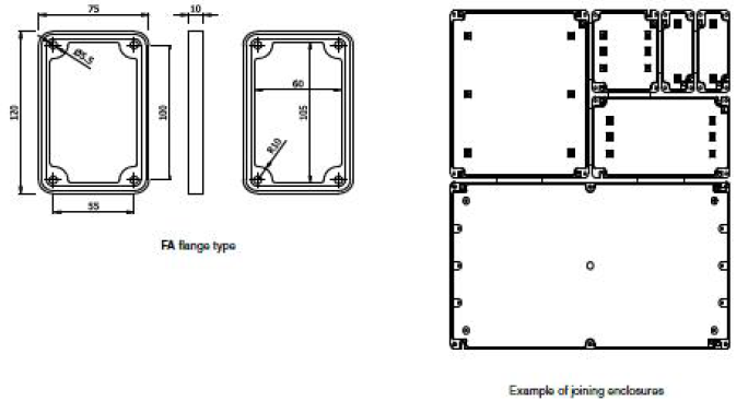
Order Specifications Table
Please refer to the below table for ordering. If you need more information, please contact our sales representative for assistance.
Numerals or letters without influence to explosion protection
-
These enclosures are primarily used with the function of cable termination unions, with terminals for derivation or change section cables, for joining long distance cables to terminals strips of motors and/or end users with entry terminals of lower section.
The internal layout of the terminals can follow different configurations and, based on client’s special requirements but always within the limits of the certificate of conformity, the terminals can be installed in different positions compared to standard ones.
The size of enclosure to be used is done by our Technical Office on basis of several parameters indicated by the client as:
? number and sizes of the cables
? number and sizes of the entries
? particular necessities regarding wiring and position of enclosures inside the plant
? temperature class
? design temperature
If the enclosure is supplied complete with cable glands we’ll take care in dimensioning them based on number and sizes of cable installed.
The terminals are installed on mounting rails to be fixed directly on dedicated supports on the basement of the enclosure or on its mounting plate.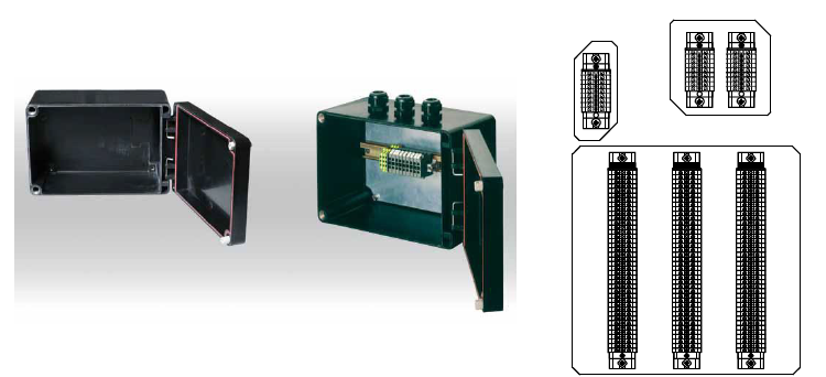
Examples of terminal disposition
The disposition of the terminals inside of the enclosure can be made in different configurations:
? straight
? diagonal
? on more rows
As per client request and always in the respect of the limits of certificate use, what maximum terminals, maximum holes for side, least distance of pertinence and dissipate power for enclosure typology, the terminals can be installed in different positions from those on described. -
These enclosures are primarily used with the function of cable termination unions, with terminals for derivation or change section cables, for joining long distance cables to terminals strips of motors and/or end users with entry terminals of lower section.
The internal layout of the terminals can follow different configurations and, based on client’s special requirements but always within the limits of the certificate of conformity, the terminals can be installed in different positions compared to standard ones.
The size of enclosure to be used is done by our Technical Office on basis of several parameters indicated by the client as:
? number and sizes of the cables
? number and sizes of the entries
? particular necessities regarding wiring and position of enclosures inside the plant
? temperature class
? design temperature
If the enclosure is supplied complete with cable glands we’ll take care in dimensioning them based on number and sizes of cable installed.
The terminals are installed on mounting rails to be fixed directly on dedicated supports on the basement of the enclosure or on its mounting plate.

Examples of terminal disposition
The disposition of the terminals inside of the enclosure can be made in different configurations:
? straight
? diagonal
? on more rows
As per client request and always in the respect of the limits of certificate use, what maximum terminals, maximum holes for side, least distance of pertinence and dissipate power for enclosure typology, the terminals can be installed in different positions from those on described. -
These enclosures are primarily used with the function of:
? Control and start-stop of apparatus as motors, fans, pumps etc. etc.
? Reading of physical greatness which flow, level, pressure, temperature,current, voltage, frequency, speed control
etc. etc.
? Offering customers a great combination of possibilities and flexibility.
The allocation of the components in the enclosure can be done following different configurations based on particular client’s requirements and always respecting the limit of certification.
The equipments on the cover are in accordance with the use in these enclosures and covered by relative certificate of component, function of the brand and selected model.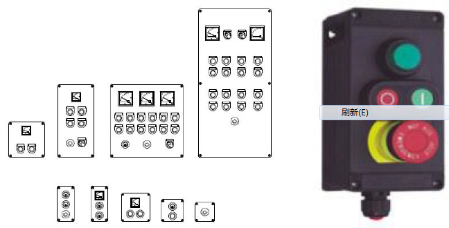
-
The equipping of dust explosion proof power distribution, switchgear and control unit combinations with electric switchgears and components is restricted so that, despite the interior power loss, the surface temperatures corresponding to the temperature class in each case suffice for the standards to be used. By means of a routine test, compliance with the temperature limits (the hottest place on the exterior of the enclosure) is ensured, corresponding to the maximum permissible surface temperature given by the manufacturer.
The enclosure and main-switch modules are available in the following materials: fibreglass reinforced polyester,stainless steel and polyester powder-coated steel. Moulded plastic enclosures are flame retardant according to UL 94 VO. All modules come in standardised sizes and can be interconnected as desired. Cable entries of all kinds can be mounted individually on the screwless plastic or brass flanges. Since these flanges
can be inserted in a snap, cable en-tri es can be easily mounted at any time. The same applies to other extensionsor modifications.
Data required for the layout of control and distribution boards We produce distribution cabinets accordint to customer requirements and basis to the project data:
? the required minimum type of protection
? as appropriate, details of the hazardous atmosphere for which the equipment must be suitable
? single line or wiring diagram
? schematic for control systems
? operating, auxiliary and control voltages
? frequency
? power and current ratings of connected loads
? quantities and types of components required, e.g. contactors, switches, circuit-breakers, fuses, thermal relays,
instruments, terminals etc
? quantity and types of cables
? number and size of conductors
? quantity and location of entries (from top, bottom, side, centre)
? environmental conditions
? method of installation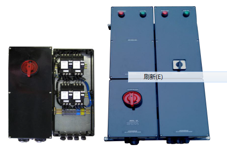
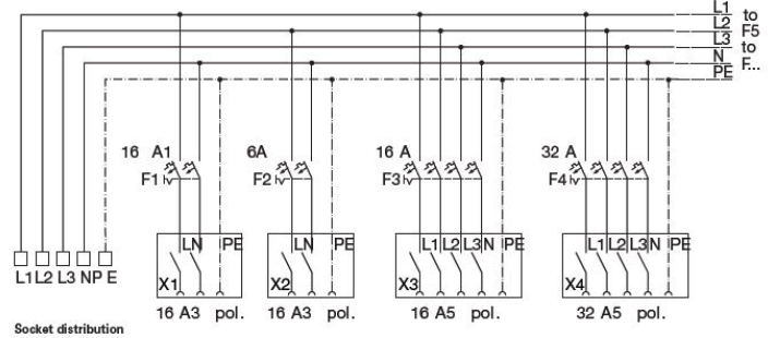
Example1:EJTC-R distribution for lighting circuits, heating circuits, socket distributions
Wiring diagram lighting distribution I heating circuits I socket distribution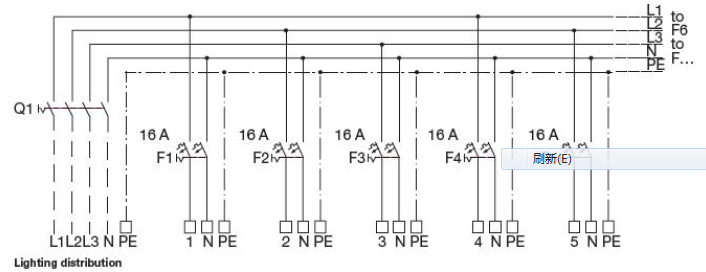

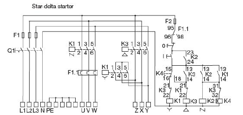
Example2:EJTC-R Complete motor starter distribution
Wiring diagram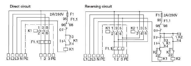


|
Please write what you need, we will contact you asap!
Give technical advice within 30 minutes | Provide program design within 24 hours | Send domestic / foreign engineers within 24/72 hours
|


